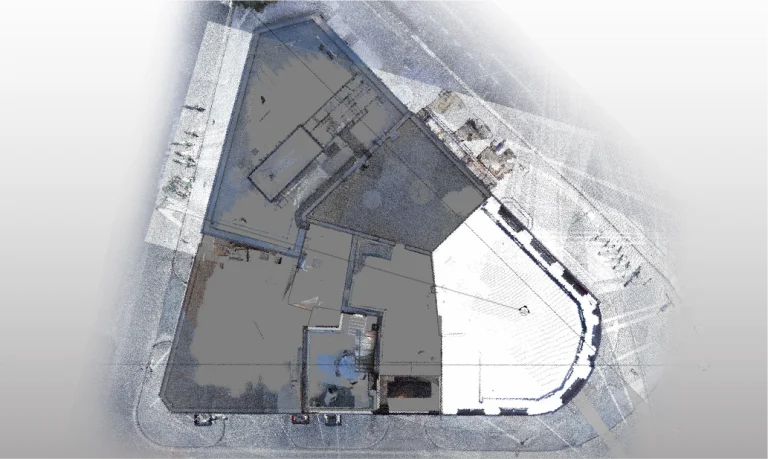
In this project, terrestrial laser scanning and aerial photography were carried out to accurately capture the existing conditions of the construction site.
The data was integrated into a BIM model for planning and coordination, complemented by robotic layout with a total station for the exact installation of elements on site, and mixed reality for visualizing and interacting with the designs.
All information was managed within a Common Data Environment (CDE), ensuring efficient collaboration and technical control at every stage.
Client:
GCP Facilities
Location:
Londres,
Reino Unido
Year:
2024
REALITY CAPTURE
DIGITAL MODELS
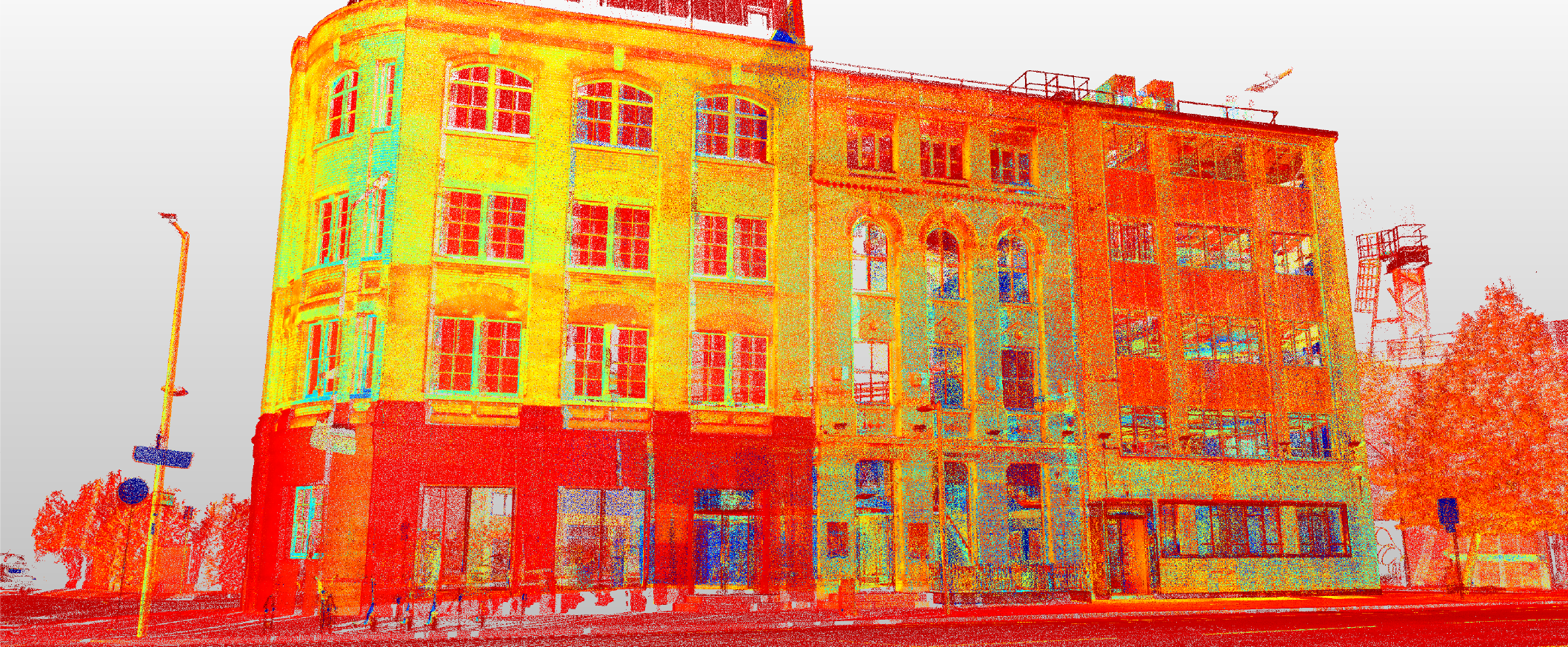
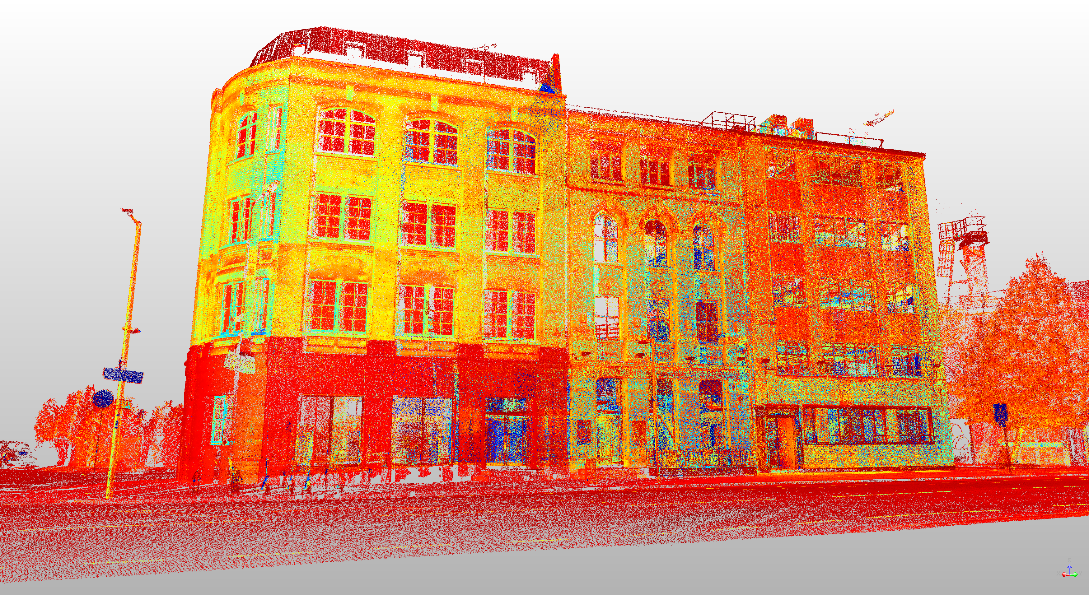
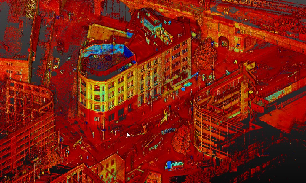
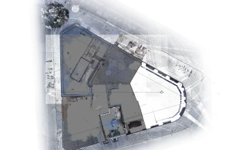
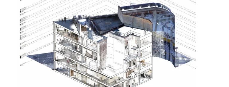
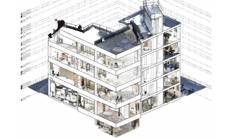
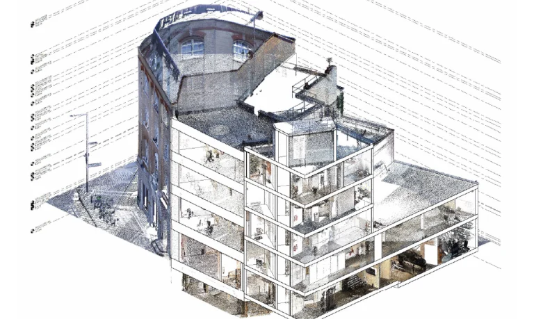
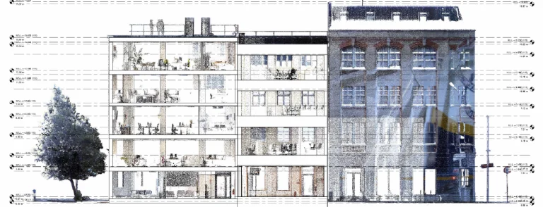
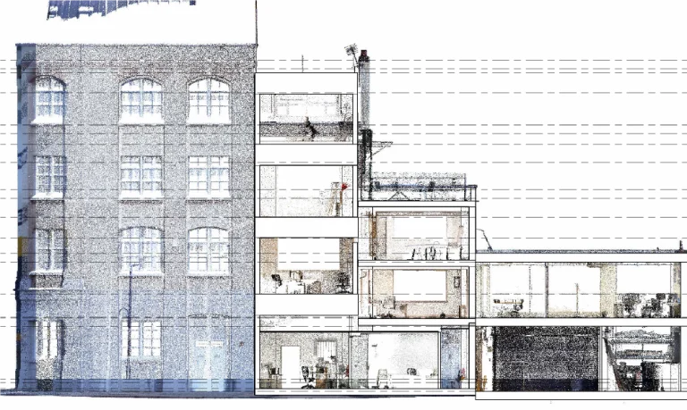
terrestrial laser scanning
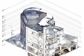
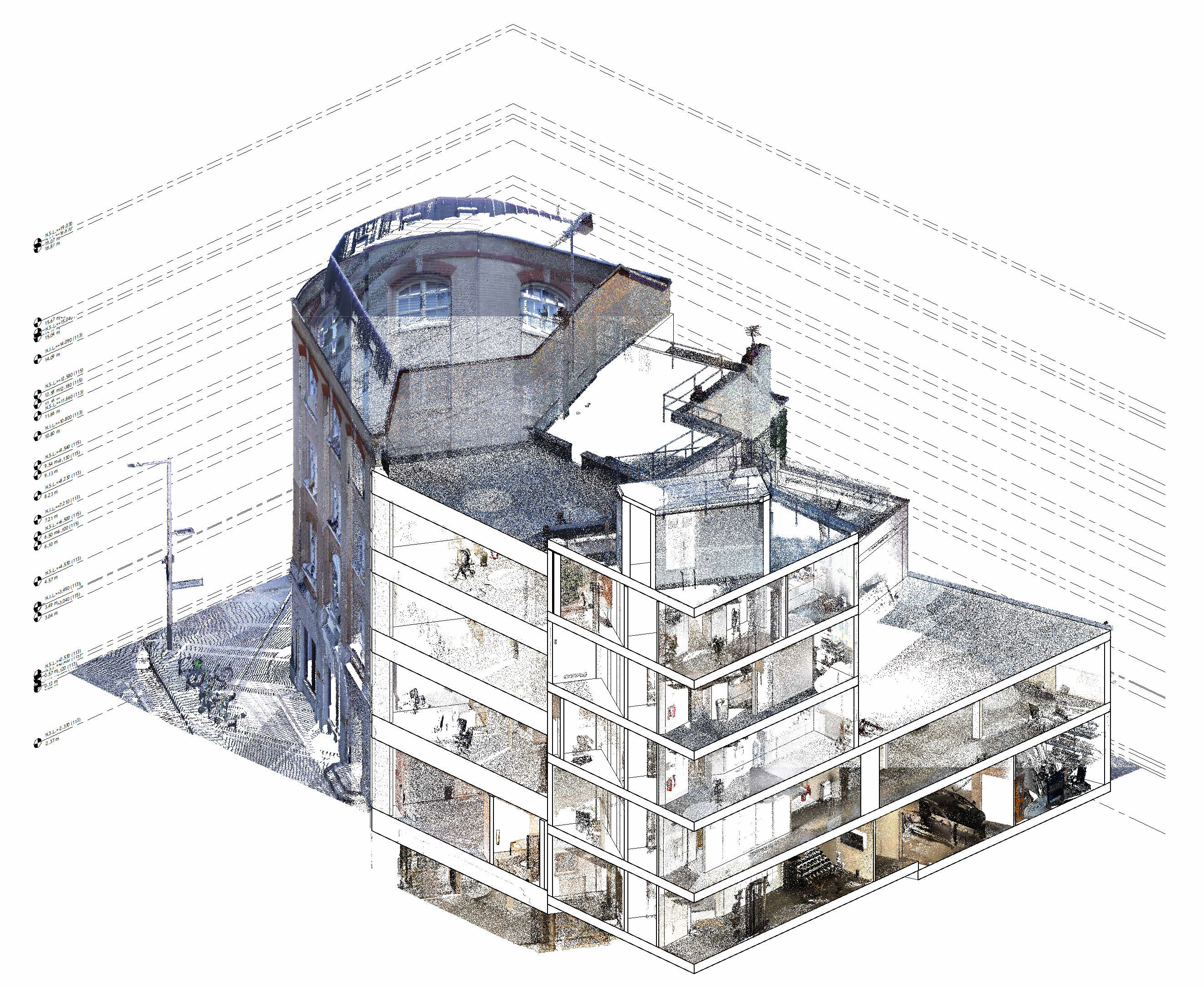
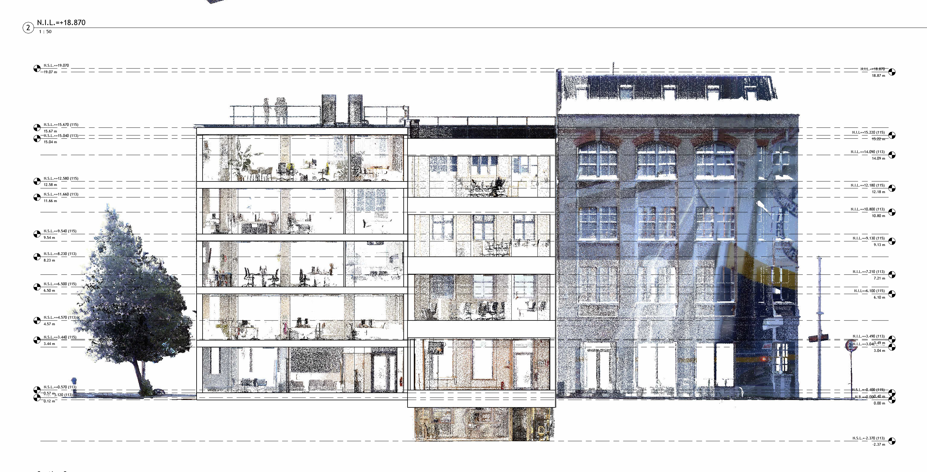
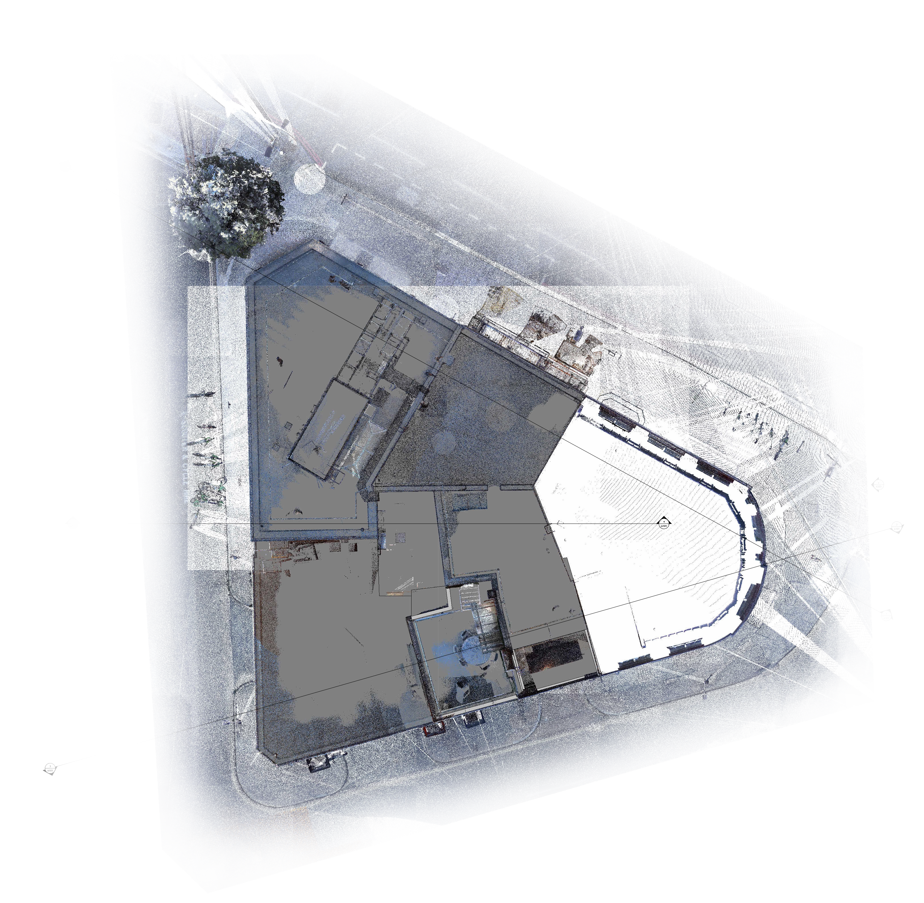
Reality capture was implemented through terrestrial laser scanning to support project management. This technology enabled the creation of a detailed three-dimensional model of the shopping mall, optimizing design accuracy, reducing errors, and ensuring that the construction was carried out in accordance with the highest quality standards.
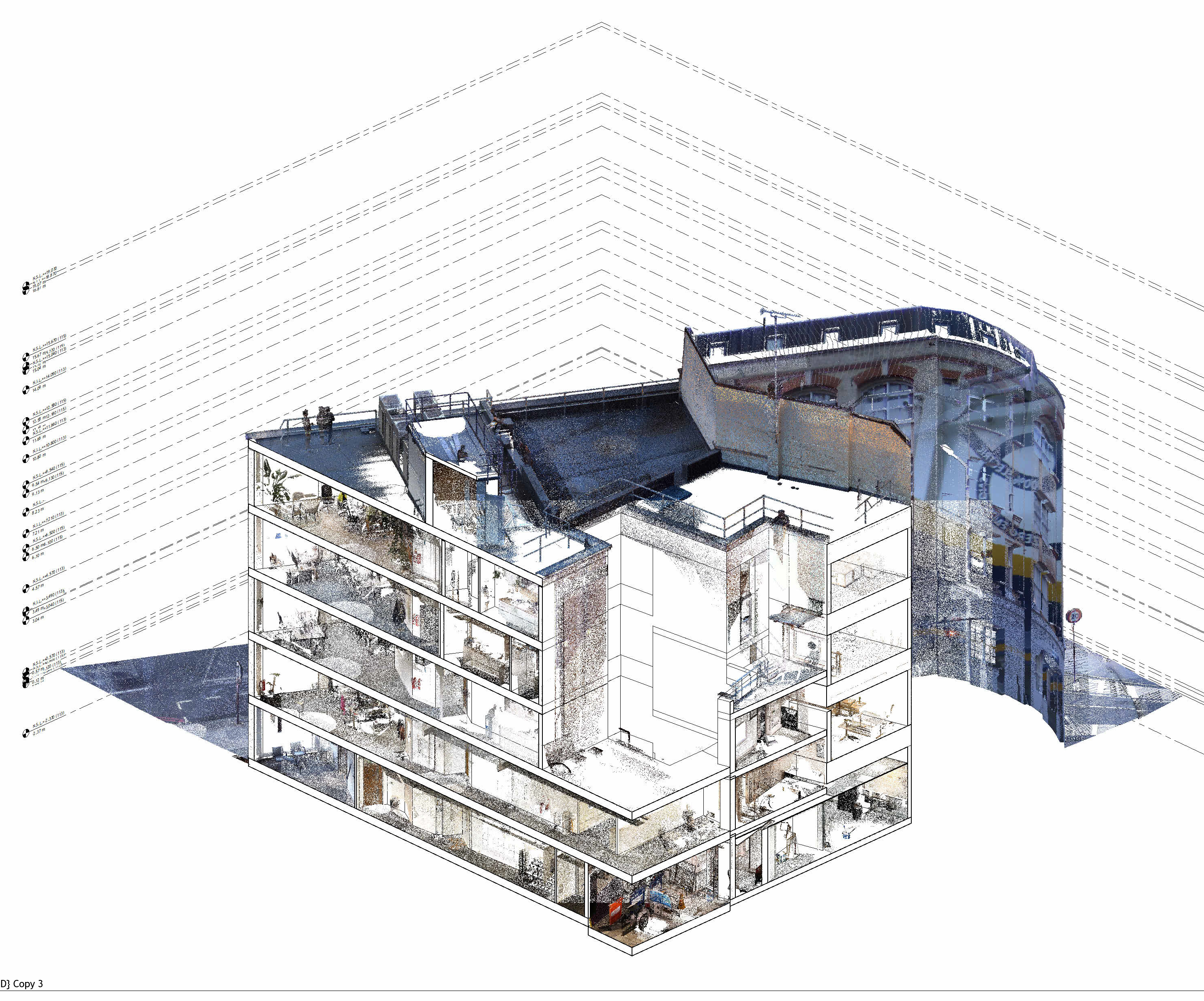
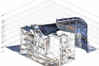
BIM (Building information modeling)
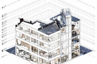
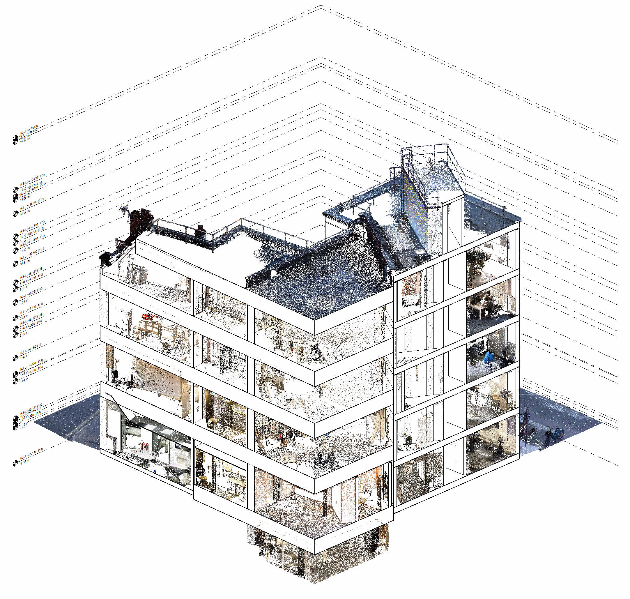
A BIM model was generated from the point cloud obtained during the survey, accurately representing the existing conditions of the construction.
This model allowed the integration of all relevant project information for use in future stages, such as modification planning, structural analysis, and maintenance, ensuring efficient management based on up-to-date data.
CAD Para As-Built
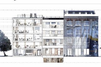
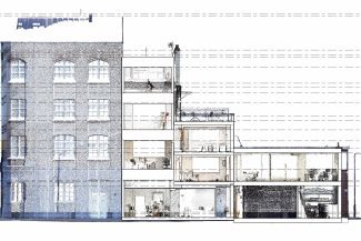
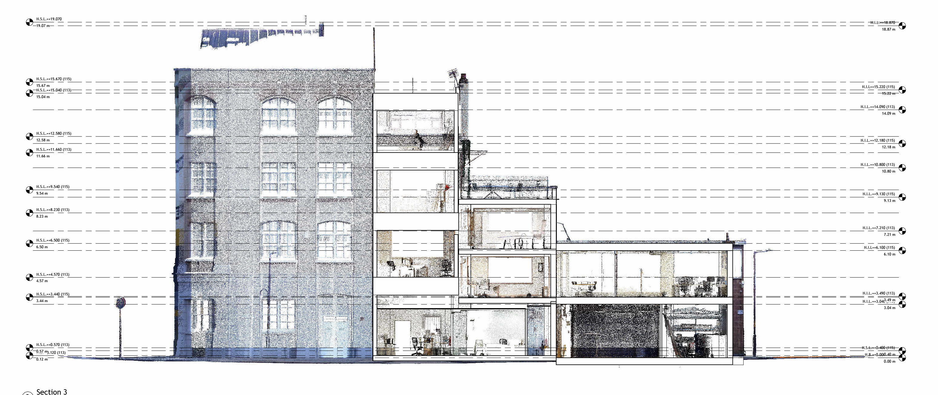
Based on the point cloud and the BIM model, As-Built drawings were produced that accurately reflect the actual conditions of the construction.
These drawings serve as precise documentation for the client, facilitating the consultation of dimensions, construction elements, and essential technical details for the project.
In this project, terrestrial laser scans and aerial photography were performed to accurately capture the existing conditions of the building. The data was integrated into a BIM model for planning and coordination, complemented by robotic layout with total stations for the precise installation of elements on site and mixed reality to visualize and interact with the designs. All the information was managed in a Common Data Environment (CDE), ensuring efficient collaboration and technical control at every stage.
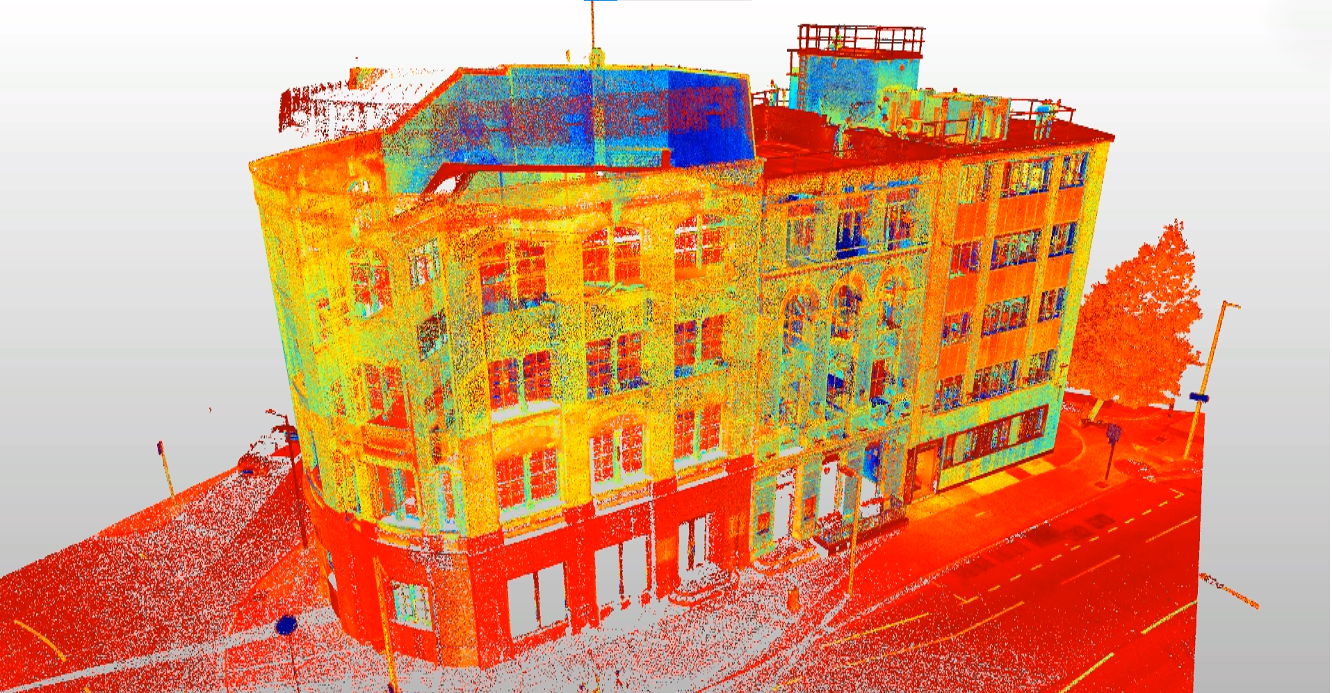
REALITY CAPTURE
terrestrial Laser Scanning
Reality capture using terrestrial laser scanning was implemented to support project management. This technology enabled the creation of a detailed 3D model of the building, optimizing design precision, reducing errors, and ensuring the construction was developed according to the highest quality standards.
DIGITAL MODELS
BIM
(Building information modeling)
A BIM model was generated from the point cloud obtained during the survey, accurately representing the existing conditions of the building. This model allowed for the integration of relevant project information for future stages, such as modification planning, structural analysis, and maintenance, ensuring efficient management based on up-to-date data.
DIGITAL MODELS
CAD (Para as Built)
Based on the point cloud and the BIM model, As-Built drawings were created, accurately reflecting the real conditions of the construction. These drawings serve as precise documentation for the client, facilitating consultation of dimensions, construction elements, and essential technical details for the project.